Hardware Onboarding
Purpose of the Hardware Role
Hardware members are responsible for building and testing the physical electronic circuits that connect sensors, microcontrollers, and medical prototypes. Your work ensures the data is accurate, safe, and reliable before firmware, AI/ML, or CAD teams can build on it.
Why This is Needed
- Ensures all hardware members understand the electrical foundations before designing medical devices.
- Builds confidence in safe wiring and measurement.
- Guarantees that PCBs and circuits you design for EMBS are reliable, safe, and functional.
Onboarding Process
- Learn → Review the Hardware learning resources
- Learning Check → Complete the Hardware Knowledge Check using the provided Equations Sheet and learning resources.
- Assignment → Follow the KiCad tutorial to design a pulse oximeter PCB.
- Deliverables:
- Schematic and PCB files.
- Generated Gerber files (zipped).
- Submit via the Hardware KiCad Submission Google Form.
- Deliverables:
- Demo → Build and test a button-activated LED circuit
- Review → A senior officer will review your assignment, knowledge check, and demo.
- Discord Role Update → Once approved your role will be updated to hardware in discord.
Skills to Learn
Circuit Basics:
- Ohm’s Law (V = IR)
- Voltage dividers & resistor networks
- Filtering with capacitors/RC circuits
- Pull-up and pull-down resistors
Sensors & Signals
- Analog vs. digital signals
- Signal noise, shielding, grounding basics
- Biosensors: PPG (heart rate), microphone (stethoscope), thermistor (temperature), IMU/accelerometer
Prototyping
- Breadboarding circuits correctly
- Soldering through-hole & basic SMD parts
- Using multimeters for continuity/voltage/current
- Using an oscilloscope to visualize signals
Safety
- Always use isolated power supplies (no direct wall current).
- Never allow current paths through the body.
- Follow Purdue lab safety protocols for soldering and electronics.
Learning Resources
Complete these in order:
Fundamentals
- Circuits
- Ohm’s Law
- Kirchhoff’s Law
- Voltage Dividers
- Capacitors
- High Pass Filter
- Low Pass Filter
- Operational Amplifier
- Safe Circuit Design
- Helpful Tool: Multisim Circuit Simulator
Hands-On Skills
PCB Design
Our Microcontroller
Learning Check
Before moving to the assignment, complete the knowledge check with the resources opened to refer to as needed:
Assignment
By the end of this assignment, you’ll know how to:
- Install and set up KiCad (industry-standard PCB design software).
- Build a schematic in KiCad
- Generate and submit your first set of Gerber files (the files PCB manufacturers use). This will give you hands-on practice with tools and concepts you’ll use in real EMBS projects.
Step 1: Install the Tools
- Download KiCad (latest stable release)
Step 2: Background Concepts Before you start, here’s what to keep in mind:
- Ohm’s Law & KVL:
- Used to size resistors for LEDs, voltage dividers, and biasing.
- RC Filters:
- A resistor + capacitor can make a low-pass filter (smooth out high-frequency noise) or a high-pass filter (remove slow baseline drift).
- Signal Acquisition in Biomedical Circuits:
- Raw signals (like heartbeats from the MAX30102 sensor) are very weak.
- We add filter networks (RC) to clean them up before amplification or digitization
- This is why you’ll see resistors and capacitors around the sensor input/output in the tutorial.
Step 3: Follow the Tutorial
- Watch and follow along with the YouTube tutorial that walks through designing a pulse oximeter PCB in KiCad.
- Components used in the design:
- SSD1306 OLED display (for output).
- MAX30102 pulse oximeter (for heart rate/SpO2 sensing).
- Arduino Nano (for processing). As you follow, make sure to replicate the schematic and PCB footprints in KiCad. Feel free to replicate or design your own layout for the PCB.
Step 4: Deliverable
- When you finish your board:
- Generate Gerber files in KiCad (File → Plot → select Gerber) and zip into a folder
- Here’s a link to how to generate gerbers compliant with JLCPCB, the manufacturer we will use.
- Once your files are generated you can upload them to JLCPCB to review the layers and more details.
- Zip your project files (Schematic and PCB files)
- Zip gerbers and project files into one folder. Format:
- Main folder
- gerbers.zip
- projectfiles.zip
- Main folder
- Submit your zipped files via the Google Form:
- Generate Gerber files in KiCad (File → Plot → select Gerber) and zip into a folder
Demo
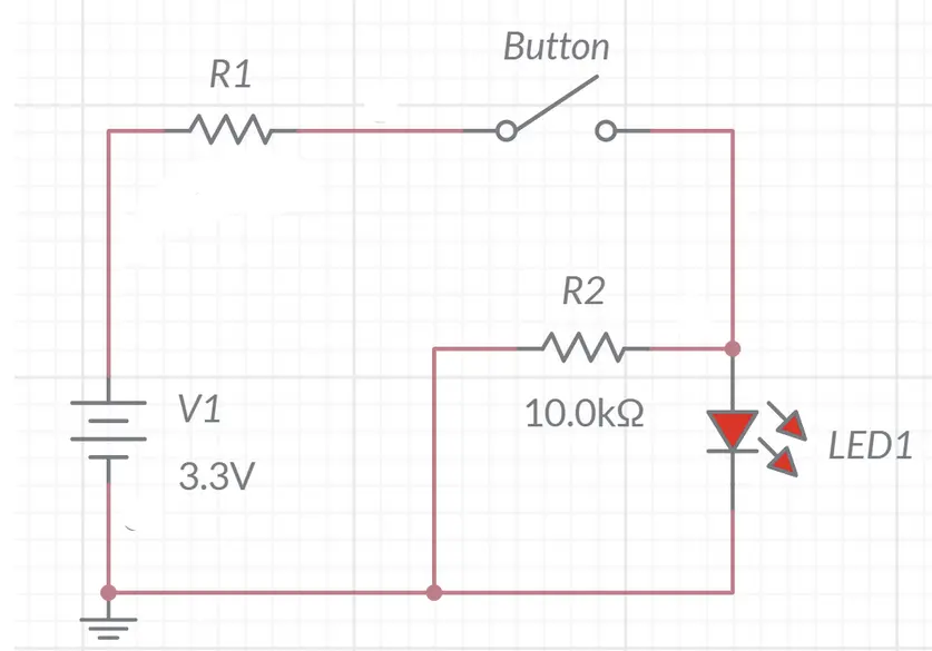
Task: Design and test button activated LED
-
Calculate the resistor value to provide the correct amount of current to the LED (look for the forward current in this datasheet)
 - Design:
- Draw the schematic and test functionality in Multisim
- Prototype:
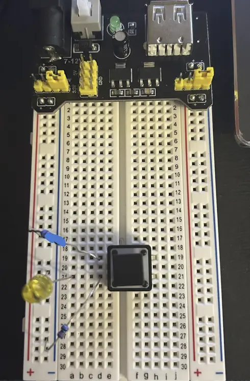
- Build the circuit on a breadboard.
-
Do NOT turn on the power supply.
- Deliverable:
- Once fully built, confirm the circuit with an officer before turning on the power supply.
- Demonstrate the button turning on the LED.